JT-DSO-LCR500


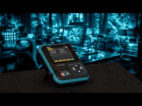



The JT-DSO-LCR500 combines a digital oscilloscope, component tester, and signal generator in a compact, handheld unit. This provides a versatile measuring instrument for development, troubleshooting, and electronics projects, covering several typical bench tasks in a single device.
The built-in oscilloscope allows for the display and analysis of time-varying signals with a sampling rate of 10 MS/s and an analog bandwidth of up to 500 kHz. Combined with various trigger modes and AC/DC coupling, it enables the quick and clear analysis of a wide range of signal waveforms.
The automatic component tester supports a wide range of electronic components and facilitates their rapid identification and testing. Among other things, it can test transistors, MOSFETs, diodes, resistors, capacitors, and inductors, making the device particularly well-suited for repair, development, and training.
The range of features is rounded out by the built-in signal generator, which provides various waveforms up to 100 kHz. This allows circuits not only to be measured and analyzed, but also to be fed directly with defined test signals—a practical, all-in-one solution for ambitious electronics projects and mobile use.
Specifications
Functions
Digital oscilloscope,
component tester,
continuity tester,
signal generator,
measurement of Zener diodes,
measurement of DS18B20 sensors
Measurements of DHT11 sensors,
Infrared decoder
Stand function
Integrated 90° foldable stand
Battery
1500 mAh lithium battery, rechargeable via USB-C
Display
2,4“ TFT color display, LED-backlight, 320x240 pixel
Available languages
English, German
Sampling rate
10 MS/s
Analog bandwidth
0 - 500 kHz
Input resistance
1 MΩ
Coupling
AC / DC
Test voltage range
1:1: 80Vpp (- 40 V - 40 V)
10:1: 800Vpp (- 400 V - 400 V)
Vertical sensitivity
10 mV/Div - 10 V/Div
Horizontal time base
10 μs - 10s
Trigger modes
Automatic, normal, single
Trigger types
Falling edge, rising edge
Triode-Measurements (hFE > 10, hFE < 600)
Amplification (hFE), base-emitter-voltage (Ube), collector-emitter reverse
cut-off current (Iceo, Ices), protection diode forward, voltage drop (Uf)
Diode-Measurements (Forward voltage drop < 5 V)
Forward voltage drop, junction capacitance, reverse leakage current
Zener-Diode-Measurements (1-2-3 testing range: 0,01 - 4,5 V, K-A-A testing range: 0,01 - 24 V)
1-2-3: Forward voltage drop, reverse breakdown voltage, K-A-A: reverse breakdown voltage
Field effect transistor measurements (JFET, IGBT, MOSFET)
JFET: Gate capacitance(Cg), drain current (Id at Vgs), protection diode forward
voltage drop (Uf)
IGBT: drain current (Id at Vgs), protection diode forward voltage drop (Uf)
MOSFET: turn-on voltage (Vt), gate capacitance (Cg), drain-source resistance (Rds), protection diode forward voltage drop (Uf)
Silicon controlled rectifier & triac measurements (Turn on voltage < 5 V, Gate trigger current < 6 mA)
Gate voltage
Capacitor measurements (25 pF - 100 mF)
Capacity, loss factor (Vloss)
Resistor measurements (0,01 Ω - 50 MΩ)
Resistance
Inductor measurements (10 uH - 1000 uH)
Inductance value, DC resistance
Battery measurements (0,01 - 4,5 V)
Voltage value, positive & negative polarity
Input voltage measurements (0 - 16 V)
Voltage value
Signal generator (Sine wave)
1 - 100 kHz, 0 - 3,3 V, 50%
Signal generator (Square wave)
1 - 100 kHz, 3,3 V, 50%
Signal generator (Pulse wave)
1 - 100 kHz, 3,3 V, 0 - 100%
Signal generator (Triangle wave)
1 - 100 kHz, 0 - 3,3 V, 50%
Signal generator (Ramp wave)
1 - 100 kHz, 0 - 3,3 V, 0 - 100%
Signal generator (DC)
0 - 3,3 V
DS18B20 measurements
temperature
DHT11 measurements
Temperature & humidity
Infrared decoding (NEC protocoll)
Display user & data code, display infrared waveform
Testing functions
Continuity test, Voltages up to 40 V
Test probe connection on the device
Micro Coaxial Connector (MCX)
Additional information
Dimensions
85 x 103 x 30mm
Weight
128 g
Items shipped
JT-DSO-LCR500, user guide, USB-C cable, 3x test clip, 3x SMD test probes, probe, crocodile clip cable, BNC adapter
EAN
4250236824918
Article No.
JT-DSO-LCR500